WHAT DO I NEED?
You'll need:
wire cutters
strippers
a voltmeter
heatshrink tube or insulting tape (sic)
2M of twin flex 1mm cross section
and a soldering iron capable of heating wires up outdoors, unless you're working in a garage. (I find that you need more heat when the wind cools the piece down outside).
You don't need to remove the fairing or anything other than the seat and the three screws holding the instruments on. I have a dB screen, which makes it easier to get to, if you have a std one you might have to take other panels off.
The unit comes with comprehensive instructions, but these aren't model-specific, so you need to compare it to a Firestorm wiring diagram to see which wires go where.
There are six wires in the unit's harness, which is just long enough to run from the clocks back to the fuse box under the seat, with little to spare, so choose your cable run wisely.
All connections should be soldered to ensure good conductivity.
THE DGV UNIT
The six wires on the DGV harness are coloured:
Orange
Brown
Red
Black
Green, and
Purple.
They're quite fine, so care must be taken to ensure they're not under any stress from bending or chafing.
WHERE DO I CONNECT THE WIRES?
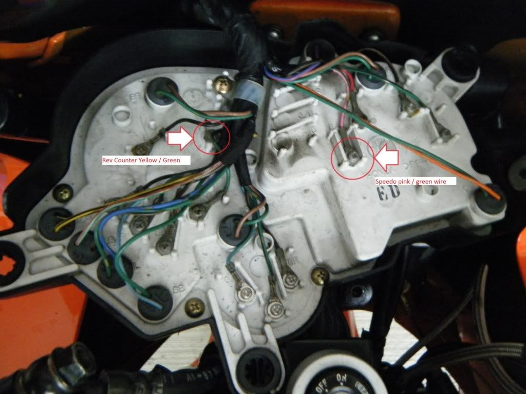
The Brown wire goes to the tacho, and the Orange wire goes to the speedo.
All of the others need to be connected to wires which meet at the fusebox under the seat near the battery, so I chose to run an extension pair of wires from the tacho and speedo back to the fusebox so that I didn't need to separate the DGV harness from its sheath, and could make all of the connections at one place.
So I took a length of ordinary electrical sheathed twin flex, 1mm cross section multi-strand, and made a short piece connecting to the correct terminals at the back of the instruments leading to a couple of bullet connectors in the same rubber protector hood as the other connection blocks behind the instruments. This is so that the instruments and DGV can be disconnected if necessary and removed as a unit.
TIP: If you use one male and one female connector on this flying lead, you can't cross-connect the wires when you disconnect it another time
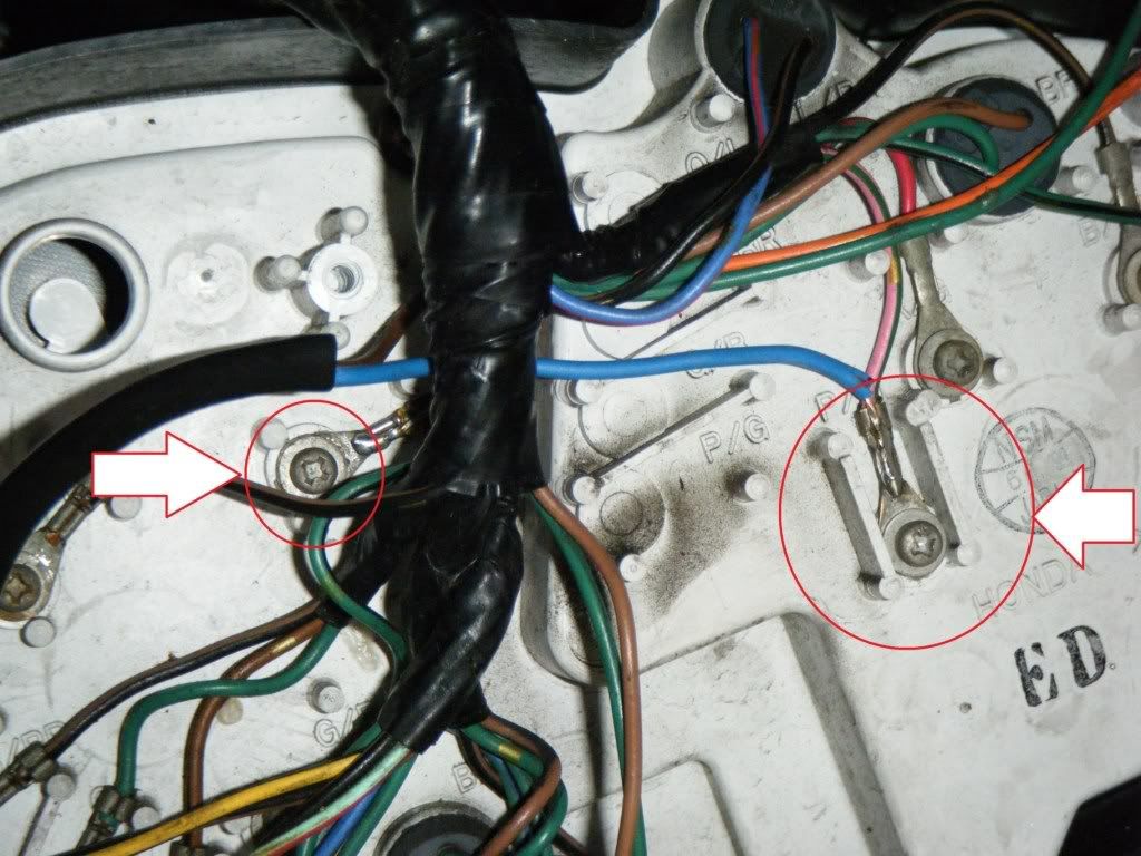
I chose to connect the blue wire from my twin-flex extension piece to the back of the speedo, onto the Honda pink with a green trace. The brown wire from my extension piece was connected to the tacho's yellow with a green trace. These are ring terminals, and a soldered end of your extension lead can be slipped under the ring terminal, and round the securing screw.
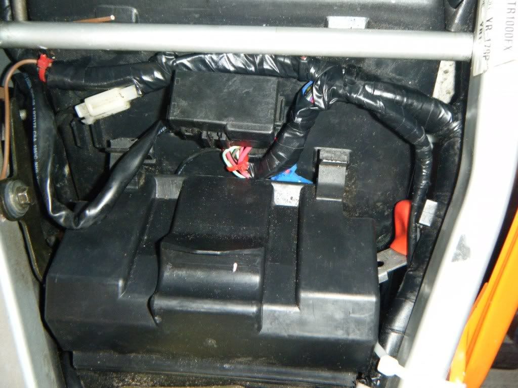
Now run a length of twin-flex back to the battery area, routing it carefully, and tying in the DGV harness as well. The DGV kit has some small cable-ties in it for this purpose. Connect the opposite gender terminals and connect it, remembering to run the cable through the rubber waterproof hood where the rest of the connectors for the instruments go, so that the connections are all in the same place.
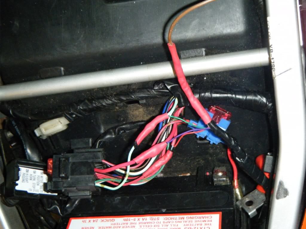
Unclip the fuse holder from the undertray, and you will have enough slack to cut and rejoin some of the wires, and connect the DGV wires. Consider how you will re-insulate the connections once made; I used heat-shrink tubing, but you have to remember to slide the heat-shrink on BEFORE soldering the wires
As the wires beneath the fuse-holder are not under strain or tension, they can be shortened by just enough to make a connection point without re-siting the fuse holder.
CONNECTIONS:
1- the first colour stated below is from the DGV harness, the second is from the Honda loom or flying lead you have made
2- RED/BLACK means a predominantly RED wire with a thin BLACK stripe or band on it.
BROWN- connect to: the BROWN flying lead (from the tacho)
ORANGE- connect to: the BLUE flying lead (from the speedo)
RED- connect to: any of the RED/BLACK wires going into the fuse box, on the input side (before the fuse)
GREEN- connect to: the LIGHT GREEN wire (the centre of three going to the diode)
BLACK- connect to: the bike's frame- you might need to make a small extension piece to find a secure connection)
PURPLE- connect to: the RED wire going into the odometer fuse (input side as before).
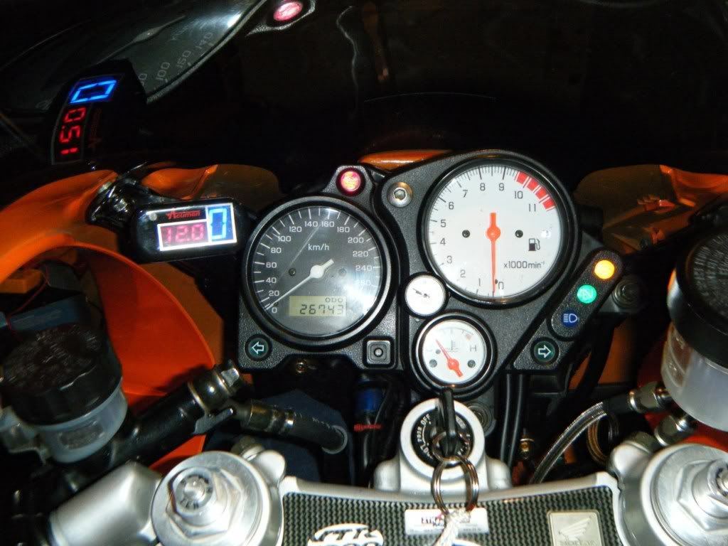
Then follow the set-up instructions which come with the unit.
I found that I had to start with step four, which sets the neutral symbol; (it doesn't matter if you do this first).
MOUNTING:
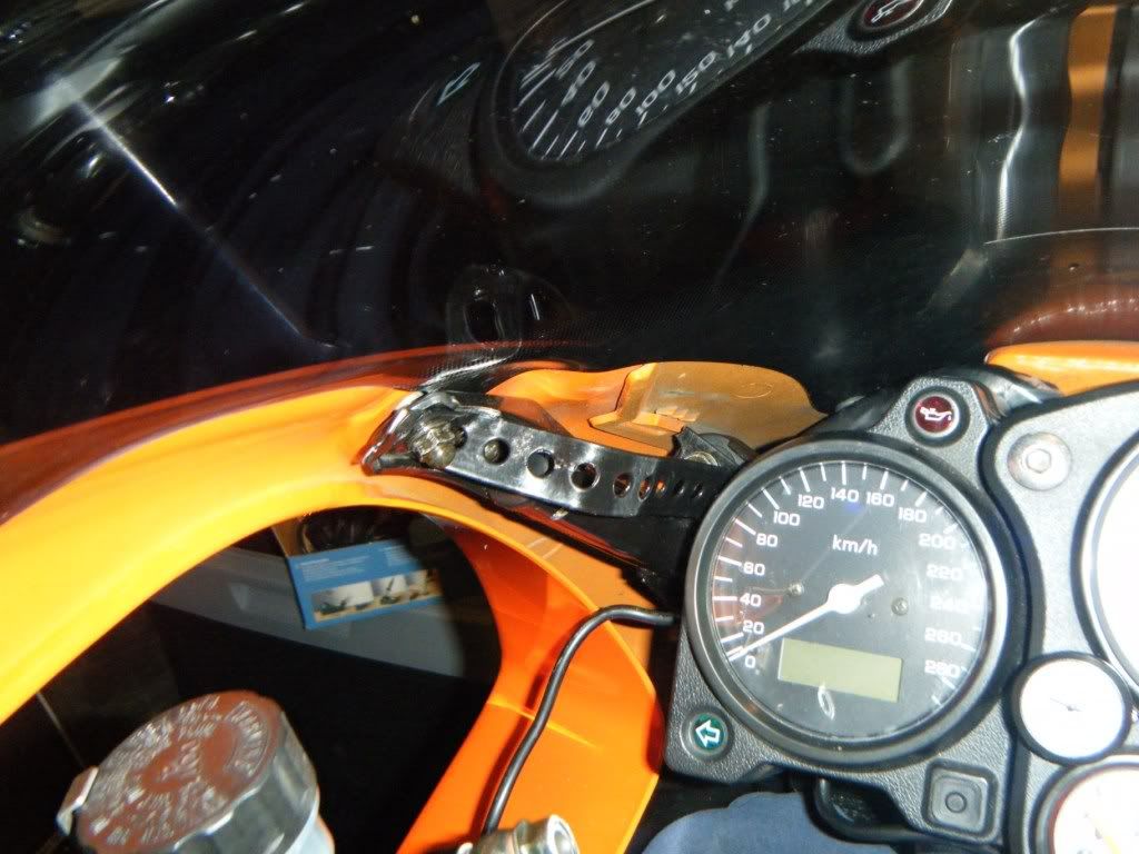
The unit comes with two sticky pads fitted with industrial Velcro, which can be used, but this doesn't fit neatly to the top of the instrument cluster as there isn't a flat surface to mount to which will clear the screen.
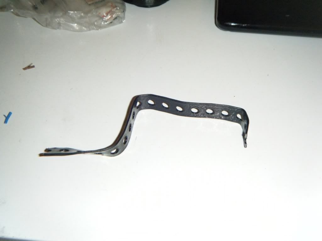
So I'm making up a small metal "Z" bracket which will fit onto the mushroom head socket screw on the instruments, and will hold the unit neatly in place.
I don't know how much this will help with fitting a gear number display only, or units from other manufacturers.
It took me about two hours, plus an hour's troubleshooting in the dark when it didn't work first time, but now I've done the hard work and identified the wires you should be able to do it quicker
Any q's PM me, I'll try to help.
Tony